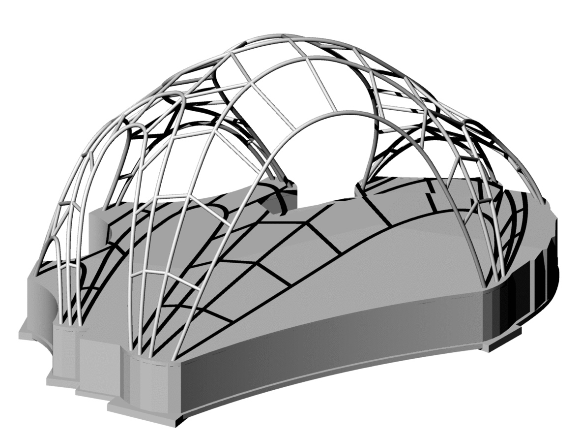
Rendering of the steel frame underlying the Chrysalis skin, and the structural concrete subfloor to which the frame is attached. (Click for a higher-resolution version.) Image © 2015 Arup.
tl;dr: I explore the steel frame underlying the skin of the Chrysalis, as designed by the structural engineering group of Arup.
This article is one in a series exploring in depth the creation of the Chrysalis amphitheater in Merriweather Park at Symphony Woods in Columbia, Maryland. For the complete list of articles please see the introduction to the series.
The previous article in this series discussed the demanding structural loads imposed on the Chrysalis by its function as a professional performance stage. In this article I explore the steel frame that underlies the skin of the Chrysalis and enables the Chrysalis to support those and other loads, as designed by Arup and fabricated and erected by the Walters Group and its subsidiary Metropolitan Walters.
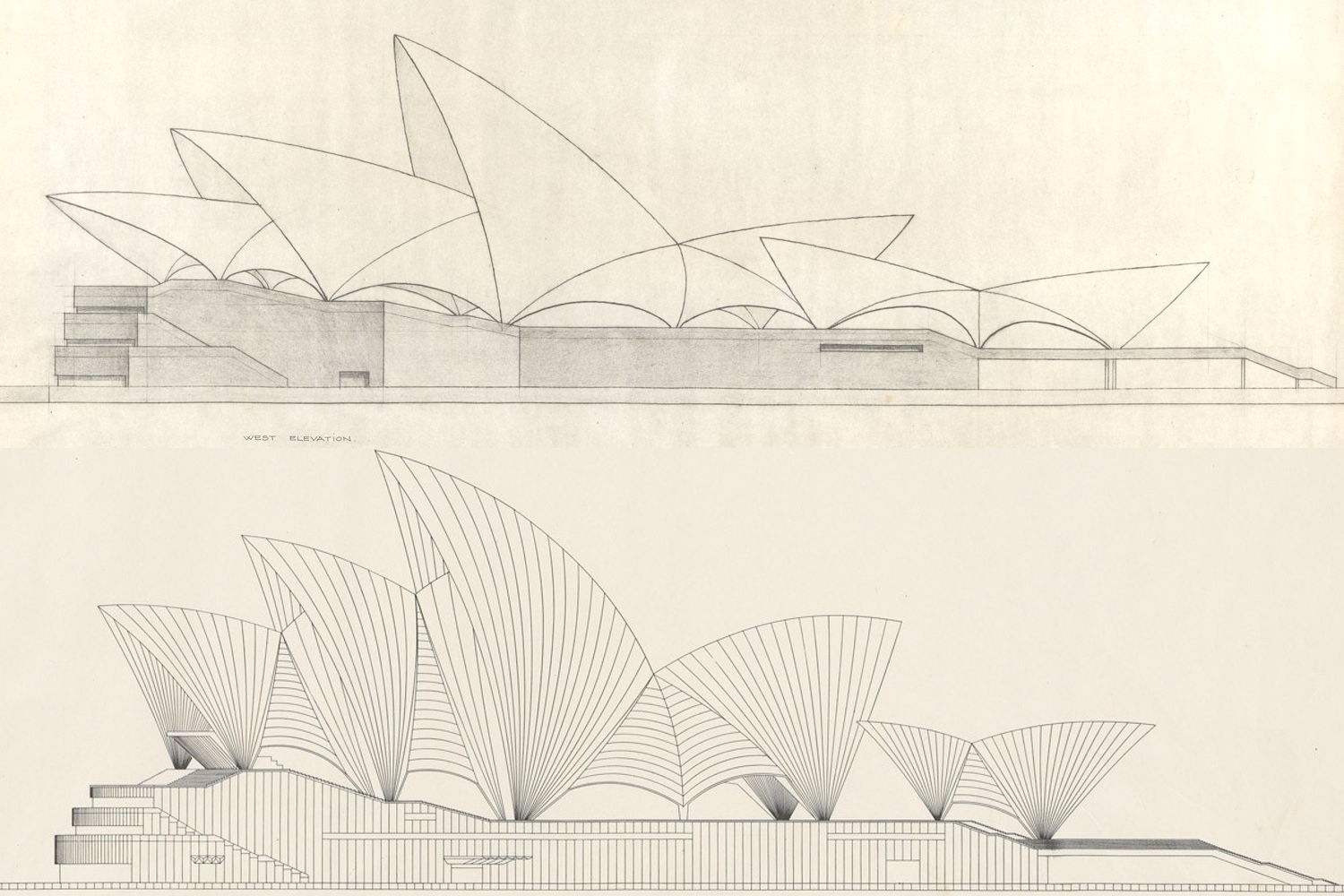
The original Sydney Opera House design by Jørn Utzon, from the drawings submitted to the design competition (top), and the final design reflecting advice from Arup on how the building shells might be fabricated (bottom). (Click for a higher-resolution version.) Note the replacement of the original continuous shell roofs with multiple series of concrete ribs. Images from the Sydney Opera House online gallery of the State Archives of New South Wales, Australia, from the competition drawings and the “Yellow Book” respectively.
Arup and structural engineering
The previous article in this series discussed the role of Arup’s theater consulting group. However, Arup began life as a consulting firm specializing in structural engineering, the task of which, according to founder Ove Arup, is “to design stable and economical structures of different kinds to meet the requirements for which these structures are needed”. In other words, the job of the structural engineer is to translate the vision of the architect into a structure that is fit for the purposes for which it is intended.
After beginning his career working on marine structures (e.g., piers, quays, and breakwaters), Ove Arup became interested in both modern architecture and the then-new technology of reinforced concrete that made new types of structures possible. He set out on his own in 1946, founding Arup and Associates as an independent consulting engineering firm. He and his colleagues soon found themselves working at the cutting edge of architectural practice, as exemplified by the firm’s work on the Sydney Opera House.
In the 1950s the government of the state of New South Wales in Australia set out to create a new center for the arts on a prominent site jutting out into Sydney Harbour. The selection committee for the design competition found itself entranced by an entry from Danish architect Jørn Utzon that featured a series of sail-like shells enclosing the two main performance spaces. (See the figure above.) Eager to get the project underway, the government authorized the start of construction, although no one had yet figured out how to build the shells Utzon had envisioned.
As the consulting engineers for the project, Arup the firm found itself at the center of the controversy over how to build what became known as the Sydney Opera House, including most notably how to analyze proposed designs to ensure their safety and stability. Working with Utzon, Arup engineers eventually found a workable solution: converting Utzon’s shells into a series of pre-cast concrete ribs of varying sizes, with the ribs arranged in sequence to form a shell-like roof.
To make the structural analysis tractable (especially given the limited computer technology available at the time), the ribs were designed so that both the sides of the arches formed by the ribs (looking at them head on) and the profile when they were connected (looking at them from the side, as in the figure above) were composed of circular arcs.1
Although the Sydney Opera House was dogged by controversies, delays, and cost overruns, the structure was eventually completed and subsequently hailed as one of the world’s iconic structures—and, along with the Sydney Harbour Bridge, the symbol of Sydney to the world. It also bolstered the reputation of Arup as a “go to” firm for clients working with world-class architects to get visionary projects built.
That reputation in turn helped Arup in its competition to attract and retain the best engineering talent. As Ove Arup said in his “Key Speech” describing his vision for Arup and principles for its operation, in practice the work of Arup or any other engineering firm can devolve into a series of mundane and potentially boring tasks: “designing endless reinforced concrete floors, taking down tedious letters about the missing bolts, changing some details for the nth time, attending site meetings dealing with trivialities, . . .—what is exciting about that?”
Thus while the Inner Arbor Trust valued Arup for its proven excellence in working with cutting edge designers to manifest totally unique structures, the Chrysalis was for Arup an opportunity to engage its staff in an interesting and innovative project, even though the scale of the Chrysalis was much smaller than that of the projects that formed the bulk of Arup’s portfolio.
One of the eight wind load scenarios analyzed by Arup, one for each compass direction. (Click for a high-resolution animated image showing all of the scenarios.) Warm colors indicate positive pressures on the shell, while cool colors indicate negative pressures (suction). Image © 2015 Arup; used with permission.
Analysing the structure
The responsibility for structural engineering for the Chrysalis fell primarily on those in Arup’s Washington DC office, including the young structural engineer Jordan Woodson and his senior mentors at Arup, Matt Larson and Brian Markham. Woodson had wanted to work at Arup ever since he was a freshman in college, and joined the firm soon after completing his graduate degree. In his time with Arup he had worked on projects ranging from the new Mexico City international airport (comprising 8 million square feet, over a thousand times the size of the Chrysalis stage) to the proposed 11th Street Bridge Park project in DC.
The task assigned to Woodson and his colleagues was to determine how the Chrysalis could be built in a manner that would maintain the artistic integrity of Marc Fornes’s design, handle the various loads placed upon it (including the skin itself, the natural forces of wind and snowfalls, and theatrical point loads), and fit within the budgetary and other constraints of the project.
This included looking at possible failure scenarios under load—as Woodson remarked, “To understand how something stands up you have to understand how it might fall down”. The high asymmetrical arch at the rear of the stage, one of the most visually striking features of the Chrysalis, required particular attention in order to ensure the overall stability of the structure.
Arup considered multiple ideas for instantiating the Chrysalis shell, including riveted aluminum or steel shingles (as in the “Pleated Inflation” structure discussed in a previous article), shingles supplemented by various types of structural reinforcements, and “sandwich panels” of metal sheets placed back to back.
In the end the configuration chosen as best meeting structural, budgetary, and other constraints was a “rib cage” or “skeleton” of steel tubes (“hollow structural section” or HSS pipe) to provide a frame underneath the shell skin, bearing the weight of the skin above and of theatrical loads hanging below. The form of the frame somewhat resembles that of the geometric mesh in the “mesh inflation” process used to create the form of the Chrysalis, with large “primary steel” tubes resembling the “lengthwise” curves of the mesh and smaller “secondary steel” tubes resembling the “crosswise” lines of the mesh.2 (See the first figure above.)
In designing the steel frame Arup performed analyses to determine the effects of various types of load, dividing the primary and secondary steel of the frame into 2-inch straight sections to simplify the computations. Under Arup’s direction BMT Fluid Mechanics of London performed extensive wind tunnel testing on a model of the structure, looking at wind forces of up to 60,000 pounds from each of the eight compass directions (north, northeast, east, and so on).
Arup then combined the pressure profiles produced from the wind tunnel testing with 33 different types of theatrical loading of up to 42,000 pounds, arising from the various configurations of the alpha and beta stages discussed in the previous article. In total the final analysis covered 350 different load scenarios.
The results of the load simulations then determined the size of the structural elements in the frame: places in the structure where the loads were greatest called for larger diameter tubes, with smaller diameter tubes used in areas with lesser loads. The final frame includes 1,700 feet of tubes for the frame, with the primary steel being 10 inches in diameter and the smaller crosswise secondary steel 8 inches in diameter.
The primary steel tubes at the bottom of the frame (comprising the “touch down” points of the shell’s arches) are attached to concrete piers, which in turn are attached to a structural concrete subfloor. The subfloor acts as a “diaphragm” to provide further rigidity to the overall structure and resist the thrust of the arches. (See the first figure above and the last figure below.) The subfloor supports the stage floor itself (comprised of hardwood panels), while underneath is located a space for storage and electrical equipment.
One of the theatrical load scenarios analyzed by Arup. (Click for a high-resolution animated image showing more scenarios.) The locations of the downward-pointing arrows correspond to the locations of the particular strong points used for each scenario. The length of each arrow indicates the magnitude of the force applied at that point. Image © 2015 Arup; used with permission.
Fabricating and erecting the frame
With Arup having designed the steel frame underlying the Chrysalis shell, the next step was to build it. The Inner Arbor Trust had tasked A. Zahner Company of Kansas City, Missouri, with overall responsiblity for the construction of the portion of the Chrysalis structure above the concrete subfloor. (The next article in this series will discuss Zahner’s role in more detail.)
Zahner then turned to the Walters Group of Hamilton, Ontario, a group of companies primarily focused on creating complex structural steel for commercial and industrial construction projects throughout North America, and its subsidiary, New York City-based Metropolitan Walters, specialists in erecting complex steel structures. (Metropolitan Walters and Arup had worked together previously on other projects, including Alice Tully Hall at the Juillard School of Music in New York City.)
As discussed above, as designed by Arup the Chrysalis frame included both long curved elements (the primary steel forming the arches of the Chrysalis and following the line of the pleats in the skin) and shorter straight elements (secondary steel) binding together the curved elements. The primary steel tubes were too long to be fabricated as single pieces, especially given their degree of curvature. Instead they were fabricated as combinations of less-curved shorter tubes, with the tubes then joined on-site to form the final curves of the frame.
Steel structural elements can be either welded together or bolted together. In order to simplify erection of structures and lower costs, the preferred procedure is to minimize the amount of welding to be done on-site. Metropolitan Walters followed this practice for the Chrysalis: the curved elements were fabricated with circular flanges welded in the shop to the 10-inch primary steel tubes and pre-drilled with holes for bolts. Matching elements were then bolted together after they arrived at the construction site.
A similar practice was followed for the secondary steel forming the straight cross pieces: in the shop short sections of 8-inch tubes with circular flanges were welded to the 10-inch primary steel tubes, matching circular flanges were welded to the ends of the straight 8-inch secondary steel tubes used for the cross pieces joining the larger elements, and holes drilled in the flanges. Bolts were again used to connect together the secondary steel and primary steel elements at the construction site.
Those familiar with traditional arches will recall that the two sides of an arch have to be supported during construction. Only after adding the top element of the arch (the “keystone” for stone arches) is the arch stable and able to stand on its own. From this viewpoint the Chrysalis steel frame is “all arches”: the entire structure was unstable while being erected until the point where it was (almost) complete. To address this, Metropolitan Walters used 16 temporary towers and supplemental guy wires to hold up partially-erected sections of the frame during construction.
Often when steel structural elements are joined they are designed so that the two elements are able to rotate somewhat relative to each other. In contrast, the bolted connections between the individual tubes of the Chrysalis frame are “moment connections”3 designed to remain rigid and act as a continuous element under load. Since the lowest elements in the frame are connected to the concrete piers and the structural concrete subfloor for the stage, the combined structure (frame plus piers plus subfloor) forms a single rigid structure able to resist loads with a minimum of deflection.
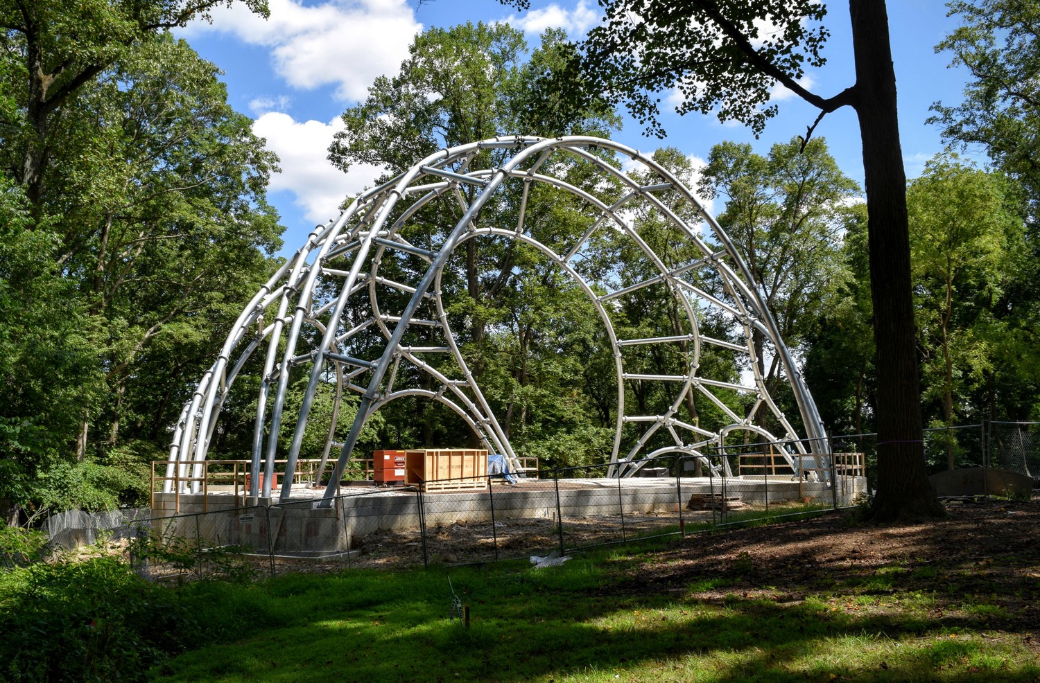
The steel frame underlying the Chrysalis skin and the concrete piers and structural concrete subfloor to which it is attached, prior to the addition of the skin. (Click for a higher-resolution version.) Compare to the figure above, and note the points at which the individual elements of the primary and secondary steel are bolted to each other. Image © 2016 Inner Arbor Trust; used with permission.
Theatrical steel and strong points
The primary and secondary steel tubes form an overall skeleton providing structural integrity for the Chrysalis. However they do not directly support the actual Chrysalis skin, nor (with some exceptions) do they directly bear theatrical loads.
As discussed in the previous article, theatrical loads for Chrysalis productions are to be hung from a set of “strong points” on the structure, each rated to bear a certain amount of load (2,200 pounds of vertically suspended weight for strong points serving the alpha stage). The strong points are designed to form a rectangular grid, but the arrangement of primary and secondary steel tubes is in no way grid-like.
The desired geometry is provided by the separate “theatrical steel,” a set of (relatively) thin steel tubes each of which runs from the front of the frame to the rear of the frame. The theatrical steel is bolted to the primary steel, using flanges welded in the shop for this purpose. The strong points themselves are in the form of small steel loops welded to the theatrical steel at regular intervals. (See the figure below.)
As hinted above, there are also a few strong points attached directly to the primary steel, mainly to support speakers to be hung at the sides of the main arch for the alpha stage. (See the strong point diagram linked to in the “For further exploration” section below.)
The combination of primary steel, secondary steel, and theatrical steel making up the frame is capable of supporting up to 58,000 pounds of equipment, assuming use of the alpha stage strong point grid, the attach points for speakers for the alpha stage, and the beta stage strong point grid.
In the steel frame of the Chrysalis Arup has provided an efficient and effective solution to the problem of handling structural loads while retaining the overall aesthetic virtues of the Chrysalis’s design. The frame also adds visual interest to the underside of the shell, complementing the dynamic green color of smooth aluminum shingles on the outer skin with the silver-gray industrial aesthetic of galvanized steel tubes and flanged, bolted splices.
The next article will discuss the outer skin of the Chrysalis and how it is attached to and supported by its steel frame.
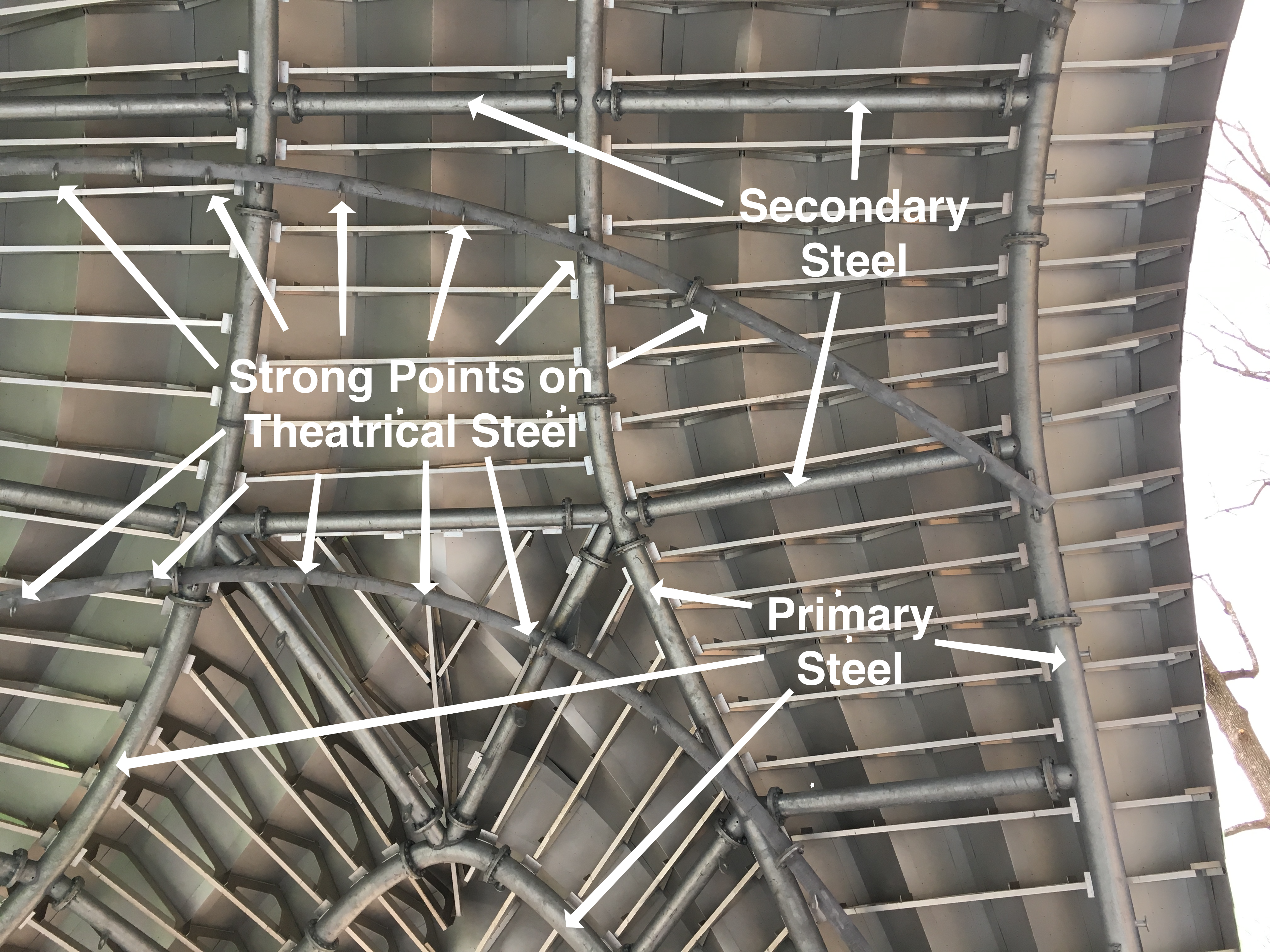
A view from the Chrysalis stage looking up at a portion of the steel frame. (Click for a higher-resolution version.) The thin straight elements positioned at regular intervals are not part of the steel frame itself; they are part of the ZEPPS units holding up the shingles of the skin. (See the next article in this series.) Image © 2017 Frank Hecker; available under the terms of the Creative Commons Attribution 4.0 International License.
For further exploration
This article is based on material from a variety of online sources, including the following:
For more on Arup, its work in structural engineering in general, and on the Chrysalis project in particular, see the following:
- Arup’s structural engineering practice
- Ove Arup’s “Key Speech” outlining Arup’s philosophy, mission, and organizational practices
- Ove Arup’s 90th birthday issue of The Arup Journal. Contains several articles and speeches by Ove Arup, including “What is a Structural Engineer.”
- “Sydney revisited,” by Jack Zunz, in The Arup Journal, 1988, Issue 1. A 1987 lecture by Arup’s lead on the Sydney Opera House.
- “Engineering is Not a Science,” by Patrick Sisson. A 2016 Curbed article that includes a good summary of Ove Arup’s life and work.
- “How Arup Became The Go-To Firm for Architecture’s Most Ambitious Projects,” by Ian Volner. A 2013 ArchDaily article that discusses Arup’s more recent projects.
- “Full STEAM Ahead” [62-minute video]. An event on November 3, 2015, sponsored by the Inner Arbor Trust to promote STEM topics associated with the Chrysalis. Includes a presentation by Jordan Woodson of Arup starting at 29:40 discussing structural analysis of the Chrysalis.
- “Chrysalis Theatre Loading Plan”. A diagram showing the location of strong points and instructions for their use.
For more on the Walters Group, Metropolitan Walters, their role in fabricating and erecting the steel frame of the Chrysalis, and structural steel in general, see the following:
- “Walters Group”. Corporate “about” page.
- “Metropolitan Walters selected as partner in Columbia Maryland’s Chrysalis project”. Press release.
- “Tubular Transformation”. A 2016 article in Modern Steel Construction describing the steel frame of the Chrysalis.
- “Erecting the Chrysalis steel” [8-minute video]. Offers a glimpse at the process of erecting the Chrysalis steel frame.
- “Structural Steel Connections,” by the American Institute of Steel Construction (AISC). A presentation discussing the various ways to connect structural steel members. Slides 16 and 17 address moment connections.
For more on the Chrysalis amphitheater and its origins in the Inner Arbor concept plan, see the following:
- Michael McCall presentation of the Inner Arbor concept plan to Leadership Howard County [33-minute video] (September 20, 2013).
- The Chrysalis portion of the Inner Arbor pre-submission community presentation (December 2, 2013).
- Michael McCall presentation to the Howard County Design Advisory Panel [20-minute video] (February 26, 2014).
For more of my opinions on and explanations of various aspects of the Chrysalis and Merriweather Park at Symphony Woods, see the Inner Arbor-related posts in the series “The Inner Arbor plan takes shape” and elsewhere on this blog. (Note that some of these posts contain outdated information relating to park features that were later dropped or revised.)
The analysis for the Sydney Opera House was done in the early 1960s. Recall from the earlier article on the design of the Chrysalis that this was before the invention of NURBS curves and surfaces and of techniques to analyze such surfaces under load. ↩︎
One major difference is that the original mesh was composed only of quadrilaterals, while the steel frame uses triangles at key points to provide increased rigidity for the structure. ↩︎
In this context “moment” is another word for force. A moment connection is named thus because it transmits forces unmodified across the connection point, with minimal deflection of the structure at that point due to so-called “bending moments” that act to rotate one element relative to the other. ↩︎